 +1 206 890 7337
 sales2@super-metals.com
Basis of Soft Magnetic Alloy-Uses of Permalloy
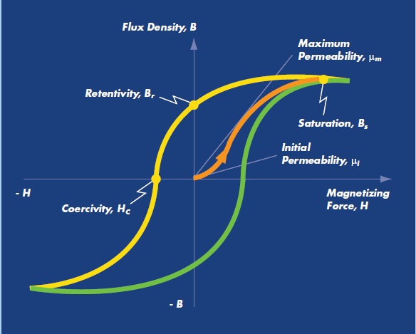
The performance of a magnet is based on a magnet field resulting in the magnetic induction of a metal or alloy. The magnetic field force H (A/m) produces magnetic induction B (Tesla) that is found by permeability µ = B/H. These correlations are determined by means of two coils enclosing a closed ring core, one coil produces the magnetic field and the other measures the induction rate. The relation between magnetic force and induction is shown by the hysteresis curve. Induction improves the field force as long as the material is fully magnetized at point Bs, also referred to as the saturation induction level. Decreasing the field force will result in hysteresis because of deviation from the curve. When the field force is minimized to zero, there is a specific extent of residual magnetic induction called as remanence. If a field force is induced in the reverse direction, the field has to approach the Hc coericivity level prior the magnetic induction is decreased to zero. Now increasing the field force, we reach Bs without following the basic curve and the hysteresis loop is closed. The shape of the hysteresis loop determines the loss of energy in a material.
Ferromagnetic materials
Iron, Nickel and Cobalt are the only ferromagnetic materials and the reason of why they strengthen the magnetic field induced externally can be understood from their electronic configuration. Considering the soft magnetic materials and their characteristics, the saturation induction rate is based on the chemical composition of the material whereas the permeability, remanence and coercivity are based on microstructure and hence on cold working, heat processing, grain size and magnitude of impurities like carbon, oxygen, nitrogen and sulfur- the whole of this should be kept at the minimum possible level. The ferromagnetic metals such as iron, nickel and cobalt create the base of the materials, irrespective of the production technique used.
Soft magnetic alloys future
The combination of versatile material’s design and the variety of shapes with the process metallurgy procedure offer a new dimension to the production of magnetic circuits. Using the isotropic soft magnetic materials, the limitations can be discarded that are caused by two dimensional steel laminations.
The soft magnetic materials are made of powdered metal particles with an electrically insulating surface. The powder is pressed using a lubricant, creating an isotropic metal. The heat processing offers stress relief offering the strength while permitting the material to keep its insulating layer around each particle separately. The insulating layer prevents the eddy current from moving across the particles when the material is subjected to a variable magnetic field hence enhancing the responsive period. In addition of use in the transformer cores, soft magnetic alloys are also used in the electric motors.
Heanjia Super-Metals produce soft magnetic alloys in forms such as wire, sheet, strip, tape, mesh etc, for use in motors.
Powder metallurgy (PM) suitability for Softmag alloys
Powder technology based procedures are fit for the production of electro-technical and electronics parts. They are outstanding for the mass production of small parts, usually with a complicated shape and the tolerance needs are normally met after sintering, preventing the requirement for subsequent calibration. The materials utilized are powder metallurgically prepared soft magnets that are same as those utilized for the rolled products and iron – phosphorous and iron-silicon alloys and ferric stainless steels. Definitely specific process factors related with the powder metallurgy cannot be discovered in the sheet components.
To product the required soft magnetic parts, it is essential to determine the material needs. Large saturation magnetization and remanence needs powder metallurgy with fine pressing features. Small coercive force and large permeability needs clean materials- a feature of the PM.
Non-sintered soft magnetic components
Uses in variable magnetic fields above 50 Hz, non-sintered soft magnetic components offer high potential and cost-effective benefit. Because of net or almost net shape and high density design of the products, the magnetic characteristics of the transformer sheets are received however at the lower price.
Specifically in the frequency range above 2kHz, eddy current losses are lower than in the equivalent transformer sheets. Additionally for the production of new electrical engines 3d magnetic flux is of great significance. These two features are offered by PM soft magnetic components.
For use in coil cores where primarily eddy losses take attention and induction and permeability are less significant, the special components are utilized in addition with an adapted procedure.
By using the different materials and with the development of advanced procedures, Heanjia have succeeded in including a vast frequency range thus a broad series of applications.
Permalloy- Special soft magnetic alloy
Permalloy represents a series of Nickel-Iron (NiFe) alloys that are heat processed to exhibit extremely higher initial permeability as compare to pure iron. They are commonly produced in thin sheet form. Permalloy series displays outstanding soft magnetic characteristics and they have been extensively used in the electronic equipments and industry.
Over the past decade the mechanical milling and alloying method have became well popular to create several equilibrium and non-equilibrium alloy phases that offer more feasibility for research and use of permalloy.
Soft magnetic alloys using milling metallurgical techniques are achieving wide spread reputation in applications of motors, compressors and other rotating equipments. The high density soft magnetic material was prepared with high induction and coercive force, having density 7.55 g/cm3 at 13 tons/cm2, with coercivity of 310 A/m, resistivity 8000 micro-ohm cm and mechanical strength 100 MPA.
Permalloy is an alloy with extremely high magnetic permeability, small coercive force, nominal core losses and small remnance by magnetic field annealing. It has applications in the magnetic shielding where fields extremely smaller than earth’s magnetism are needed. The bulk volume applications involving the use of lamination or tape wound cores are ground fault interrupter and modem transformer cores. Permalloy is used in the diverse high performance transformer core applications for example recorder heads and audio transformers. The control on the quenching rate while heat processing and superimposition of the different bake treatments are followed to produce the most suitable magnetic property for the desired application.
The small magnetostriciton is important for industrial applications, allowing its use in thin films that involve variable stresses which otherwise result in a disastrously extensive variation in the magnetic characteristics. The electrical resistivity of Permalloy may change up to 5% on the base of strength and direction of an applied magnetic field.
Permalloy has face centered cubic crystal structure with a lattice constant of about 0.355 nm in the nickel content about 80%. It doesn’t have sufficient ductility or workability hence the applications demanding elaborated shapes like magnetic shields are constructed using the high permalloy grades for example, Mu metal. Permalloy is utilized in the transformer laminations and magnetic recording heads.
Discovery
Permalloy was discovered in the beginning of 20th century for inductive compensation of telegraph wires. Earlier in 1860, long conductors were used in transatiantic submarine telegraphs cables that caused damage and resulted in reduced signaling strength merely 10 to 12 words per minute. The suitable media for sending signals without loss were initially determined in 1885 by Oliver Heaviside. In 1902 the signal loss in cable was attempted to compensate by winding it with the iron wire, improving the inductance and using it as a loaded line to decrease loss. Although iron didn’t possess sufficiently high permeability to recompense the transatlantic length cable. Subsequent to a prolong search, permalloy was found in 1914 by Gustav Elmen in Bell Labs who discovered that it possesses larger permeability as compare to silicon steel. Further in 1923, he realized that the permeability can be further improved by heat processing. Winding permalloy tape could significantly increase the signal transmission speed. After the development of Permalloy, several applications in the electronic industry were discovered that involved the required features of permalloy.
Soft magnetic alloys specifically refer to materials that have characteristics such as small coercivity, small magnetocrystalline anisotropy and suitable saturation magnetization. It is usually highly desirable to keep small or zero magnetostriction, as any application subjected to an ac field will suffer from losses as field energy is changed into mechanical energy. Soft magnetic thin layers are normally formed from 3d transition metal ferromagnetic elements such as iron, cobalt and nickel and their alloys, specifically NiFe and CoFe.
The magnetic characteristics of soft magnetic thin layers are dominated by shape anisotropy, as the contribution of other anisotropy terms to the total energy is small. In case of metallically regular films, this results in magnetization stated in the film plane. If a well specified columnar structure is produced, then shape of columns specifies the anisotropy and it can cause any direct axis of magnetization perpendicular to plane.
Magnetic material losses
For use of ferromagnetic materials in the variable magnetic fields with the passage of time as those found in alternating current applications, attention should be given to the influence of frequency on the behavior of the magnetic material. The calculated permeability is influenced by variable frequency. Moreover, the losses linked with materials that are subjected to the variable magnetic field should be taken into account.
Core loss
An essential factor that grabs attention in determining the suitable magnetic material in AC applications is core loss. This term states the power loss in the core as it is subjected to the variable magnetic field. Generally, Core loss should be reduced to minimum by increasing the energy efficiency. Core loss can be stated as the total of hysteresis loss and eddy current loss.
The hysteresis loss can be referred as the energy required to sweep the domain walls. When a material is subjected to an alternating magnetic field, every cycle around the hysteresis loop needs a specific magnitude of energy that is directly associated to the area swept by hysteresis loop. It is based on the application frequency and hysteresis loop area of alloy. It is specified as:
Hysteresis Loss = Kh x loop area x f(5)
Here Kh represents a constant and f is frequency of alternating magnetic field. By decreasing the hysteresis loop area of the material, hysteresis loss value also decreases. Normally it also decreases by reducing the coercivity.
The other factor responsible for core loss is called as eddy current loss. While subjecting a ferromagnetic material to an alternating magnetic field, electricity is produced by induction in material. This current value generally called as eddy current is based on the frequency of applied magnetic field, material resistivity, induction strength and convenience of circulating current through the material. The generation of this current results in increasing the heat production in the core material. The role of the apparent loss in the core by eddy current is generally stated as eddy current loss. The eddy current loss is specified as:
Eddy current loss = Ke x [d2xB2xf2]/p
Where Ke is a constant, d is a thickness of material, B is the induction level, f is frequency and p represents electrical resistivity of the material. The net core loss is calculated over a wide frequency range, the contribution of every component of loss to the total core loss changes. As hysteresis loss and eddy loss are functions of frequency to the first and second power, hysteresis enhances the small frequency losses and eddy currents overcome the high frequency losses.
Permeability
Eddy currents also influence the measured permeability of a magnetic material that is subjected to the variable magnetic field. The Eddy currents circulate in a way to establish a magnetic field in the opposite direction of the applied field. Greater the eddy currents larger the opposition of magnetic field. The result is a smaller net magnetic field practically influencing the core material. The decreased apparent magnetic field creates a smaller measured induction level. The permeability is specified as following:
µ = B/ H
To decrease the eddy currents, lamination steels are rolled as thin sheets to enhance the resistance and increase the penetration depth of magnetic area. The sintered milled material is not suitable for AC applications for suitable functionality.
Insulated Iron Powder
It has been the need of metallurgists to replace the lamination steel with powder metal parts. The lamination steels are punched to shape and are stacked and welded. The powder metal parts can be produced directly to shape in single process. The production of powder metal procedure for replacing lamination steel was inspired by the fact that eddy current core loss can be limited to an individual particle in a compact sizes and coating electrically isolates these particles. Chief uses of such materials are in equipments like motors, induction coil cores and actuators.
High speed interconnect applications
The mutual inductance and self inductance of global interconnects are essential to model in deep submicrometer very large integration (VLSI) designs. The unavailability of suitable mutual magnetic field shielding reduces the highest unbuffered interconnect line length. Permalloy films are included into planar transmissions utilizing a CMOS – compatible process. The line properties describe that eddy current effects are the limiting factors for the high frequency permalloy applications when the ferromagnetic resonance are restrained by geometry design. Patterning permalloy films suitably improve their application to over 20 GhZ. The line attribute impedance are around ~90 ohm. Below 50 mA dc current biases, line parameters do not alter significantly. Additionally, patterned permalloy decreases the magnetic field coupling among two consecutive transmission lines around 10dB in a specific design. The current carrying capability and magnetic field shielding features demonstrate that permalloy loaded lines are fit for high speed interconnect applications in CMOS technologies.
Permalloy thin layers have a significant effect on the saturation magnetization is crucial to realize the magnetic nature of these alloys.
Common Uses
The suitable properties of thin permalloy layers are significant in the diverse research and in devices. It is used in transformer cores, magnetic head cores, magnetic shield case, head case, cassette tape magnetic shielding, watch components, transducers, car speedometer, integrating watt hour meter, magnetic sensor, floppy disk drive, car sensor, VTR, VTR camera, diaphragm. Permalloy is used in transformer laminations and magnetic recording head sensors. It is also utilized in transformer laminations and magnetic recording head sensors.
Permalloy is commonly used in the production of thin pieces for lamination to fabricate transformer cores. The proportion of nickel may vary from 35 to 90% on the base of properties required, and is around 78% for small power transformers.
Property data
Chemical composition
| C | Si | Mo | Mn | Ni | Fe |
| 0.02 % | 0.35 % | 4.20% | 0.50% | 80% | Rem |
Physical properties
| Specific gravity | 8.74 |
| Density | 0.3160 lb/in3 |
| Mean specific heat capacity | 0.1180 Btu/lb/of |
| Mean coefficient of thermal expansion | |
| -103 of to 77 of | 6 x 10(-6) in/in/ of |
| -58 of to 77 of | 5.94 x 10(-6) in/in/ of |
| -11 of to 77 of | 5.78 x 10(-6) in/in/ of |
| 77 of to 122 of | 6.83 x 10(-6) in/in/ of |
| 77 of to 212 of | 6.89 x 10(-6) in/in/ of |
| 77 of to 392 of | 7.09 x 10(-6) in/in/ of |
| 77 of to 572 of | 7.22 x 10(-6) in/in/ of |
| 77 of to 752 of | 7.39 x 10(-6) in/in/ of |
| Thermal conductivity | 240.1 BTU –in/hr/ft2/ of |
| Modulus of elasticity (E) | |
| Subsequent process annealing at 870oC, in tension | 31.4 x 10(3) ksi |
| Cold drawn, in tension | 33.7 x 10(3) ksi |
| Hydrogen annealed at 1177oC, in tension | 33.3 x 10(3) ksi |
| Electrical resistivity at 70of | 349 ohm-cir-mil/ft |
| Coefficient of electric resitivity at 0 to 930 of | 6 x 10(-4) ohm/ohm/of |
| Curie temperature | 860 of |
| Melting point | 2650 of |
| Coercivity | 0.00800 to 0.0200 Oe |
| Highest permeability | 200000 |
| Residual induction | 3500 G |
Average coefficient of thermal expansion
| Temperature | Coefficient | ||
| of | oC | 10(-6)/ of | 10(-6)/oC |
| -103 of to 77 of | -75 oC to 25 oC | 6 x 10(-6)/ of | 10.8 x 10(-6)/ of |
| -58 of to 77 of | -50 oC to 25 oC | 5.94 x 10(-6)/ of | 10.7 x 10(-6)/ of |
| -11 of to 77 of | -25 oC to 25 oC | 5.78 x 10(-6)/ of | 10.4 x 10(-6)/ of |
| 77 of to 122 of | 25 oC to 50 oC | 6.83 x 10(-6)/ of | 12.30 x 10(-6)/ of |
| 77 of to 212 of | 25 oC to 100 oC | 6.89 x 10(-6)/ of | 12.40 x 10(-6)/ of |
| 77 of to 392 of | 25 oC to 200 oC | 7.09 x 10(-6)/ of | 12.76 x 10(-6)/ of |
| 77 of to 572 of | 25 oC to 300 oC | 7.22 x 10(-6)/ of | 13 x 10(-6)/ of |
| 77 of to 752 of | 25 oC to 400 oC | 7.39 x 10(-6)/ of | 13.30 x 10(-6)/ of |
Magnetic characteristics
DC magnetic characteristics
| Form | µ at B = 40 G | µ max | Hc from H =1 oersted |
| Bar, wire | 50,000 | 200,000 | 0.02 |
AC magnetic characteristics, 60 Hz
| Thickness | µ 40 G | µ 200 G | µ 2000 G | |
| Inches | Mm | |||
| 0.025 Inches | 0.635 Mm | 35,000 | 40,000 | 55,000 |
| 0.014 Inches | 0.356 Mm | 55,000 | 65,000 | 95,000 |
| 0.006 Inches | 0.152 Mm | 65,000 | 85,000 | 135,000 |
| 0.002 Inches | 0.051 Mm | 70,000 | 90,000 | 220,000 |
Mechanical characteristics
| Form | Tensile strength | Yield strength | Proportional limit | % elongation | % reduction in area | Hardness Rb | |||
| Ksi | Mpa | Ksi | Mpa | Ksi | Mpa | ||||
| Bar | As cold drawn | ||||||||
| Bar | 97 ksi | 669 Mpa | 69 ksi | 414 Mpa | 19 ksi | 131 Mpa | 37 % | 71 % | 97 Rb |
| Bar | Hydrogen annealed at 2050of or 1121oC | ||||||||
| Bar | 79 ksi | 545 Mpa | 22 ksi | 152 Mpa | 19 ksi | 131 Mpa | 64 % | 70 % | 62 Rb |
| Bar | Subsequent process anneal at 1600of or 871oC | ||||||||
| Bar | 90 ksi | 620 Mpa | 33 ksi | 228 Mpa | 28 ksi | 193 Mpa | 57 % | 74 % | 85 Rb |
| Strip cold drawn | 135 ksi | 931 Mpa | – | – | – | – | 4 % | – | 100 Rb |
| Strip Hydrogen annealed at 2050of or 1121oC | 77 ksi | 531 Mpa | 21 ksi | 145 Mpa | 15 ksi | 103 Mpa | 38 % | – | 58 Rb |
| Strip (Subsequent process anneal at 1600of or 871oC) | 98 ksi | 676 Mpa | 38 ksi | 262 Mpa | 35 ksi | 241 Mpa | 38 % | – | 85 |
| Condition | Modulus of elasticity (in tension) | Izod impact | ||
| Cold drawn | 33.7 x 10(3) ksi | 232 x 10(3) MPa | 120 ft-lb | 163 J |
| Hydrogen annealed at 2050of or 1121oC | 33.3 x 10(3) ksi | 230 x 10(3) MPa | 85 ft-lb | 115 J |
| After process anneal at 1600of or 871oC | 31.4 x 10(3) ksi | 217 x 10(3) MPa | 85 ft-lb | 115 J |
Heanjia Super-Metals produce Permalloy alloy in the following forms in the standard and tailored specifications:
Wire, Sheet, Strip, Ribbon, Tape, Mesh